Odometry, Math and Importance.
Odometry is a method for robots to estimate their position and orientation (pose) by measuring the movement of their wheels. This process is like a robot keeping track of its steps to figure out where it is. Odometry is a core concept in robotics and is used for various purposes, including navigation and control.
Odometry is particularly useful in situations where robots lack access to external positioning systems like GPS or rely on sensors like cameras or laser rangefinders. It provides a way for the robot to estimate its position based on its own motion.
Odometry relies on the integration of wheel velocities over time. By measuring how much the wheels have rotated, odometry algorithms can determine the robot's change in position and orientation. However, it's important to note that odometry errors accumulate over time due to wheel slippage, uneven surfaces, and inaccuracies in sensor readings.
How Odometry Works
Odometry comes from the Greek words öðóç [odos] (route) and μsτpov [metron] (measurement) which literally mean:"measurement of the route".
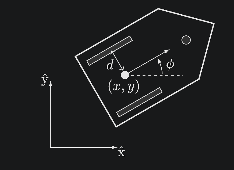
The odometry problem can be formulated as: given an initial pose of at some initial time, find the pose at any future time

Given:
Find:
When is small enough to consider the angular speed of the wheels constant, the pose update can be approximated as a simple sum.
The process can then be applied iteratively to find the pose at any time, and at each iteration using the previous estimate as an initial condition.
Imagine a robot with two wheels driven independently by motors, like a differential drive robot. These robots are commonly used in robotics due to their simplicity and maneuverability. To implement odometry, these robots typically use wheel encoders.
Wheel Encoders
Wheel encoders are sensors that measure the rotation of a wheel. They work by detecting pulses as the wheel rotates, allowing the robot to keep track of how far each wheel has turned. By combining this information with the robot's kinematic model, it can estimate its position and orientation.
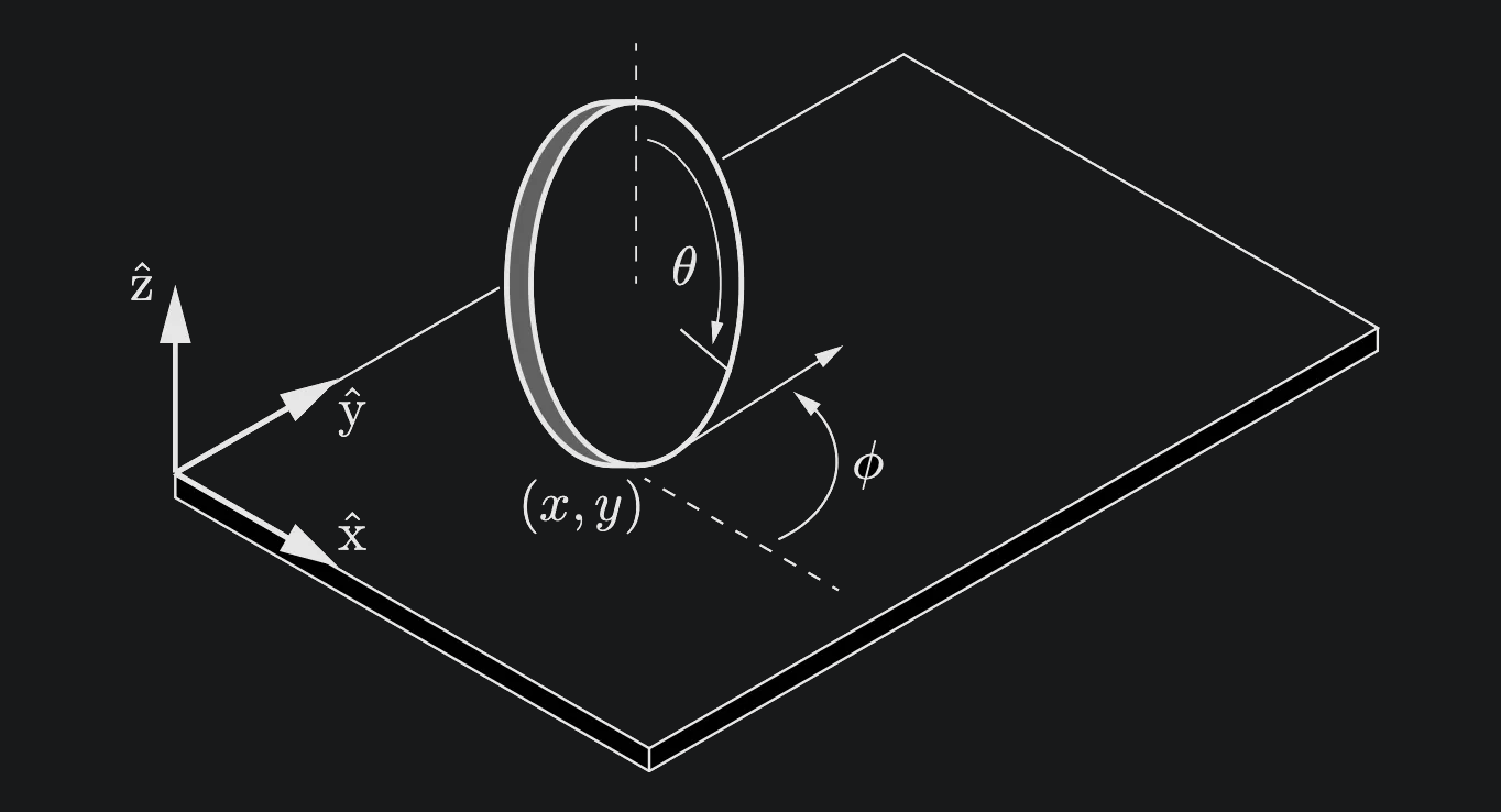
Although there are various implementations, the operation principle of wheel encoders is simple. We can utilize markers on the wheels to work it out. Knowing how many markers there are in a whole circumference, we can derive how much each wheel rotated by just counting the pulses in each of the k-th time interval.

This means Wheel rotation (in where radians for one pulse.
By dividing the total rotation by delta , we can then measure the average wheel angular speed in that time frame.
Angular speed then can be represented by . Have this for both wheels on a non-holonomic robot with two wheels, you get yourself to components and to represent the left and right wheels.
Here's a step-by-step breakdown of Odometry for Implementation
There are four compartments on creating an odometry system for robots (at least from what I've realized). You attempt to measure the wheel rotations, calculate the wheel distances, estimate pose, update overall pose of robot.
Measure Wheel Rotations: Using wheel encoders, the robot measures how much each wheel has rotated since the last measurement. These measurements are represented as indicating the change in wheel angle.
Calculate Wheel Distances: Knowing the wheel radius (R), the robot calculates the distance traveled by each wheel using the formula
Estimate Position and Orientation Changes: Based on the wheel distances and the robot's kinematic model (which takes into account factors like the distance between the wheels), the robot estimates its change in position and orientation .
Update Overall Pose: The robot adds the calculated changes to its previous position and orientation estimates to obtain its current estimated pose.
This model allows us to perform the pose update once we determine its parameters, which are the wheel radii, which we assume identical, and the distance between the wheels, or the baseline.
Parameters
- : wheel radius
- : baseline (distance between wheels)
Implemented Odometry for ROSpy
Read More HereChallenges in Odometry
While odometry is a powerful tool, it faces several challenges:
- Error Accumulation: Odometry errors, primarily caused by wheel slippage and inaccuracies in sensor readings, accumulate over time, leading to drift in the estimated pose. This drift can make the robot's position estimate increasingly unreliable over long distances or extended periods.
- Kinematic Model Accuracy: The accuracy of the kinematic model is crucial for precise odometry. Any discrepancies between the model and the real robot, such as variations in wheel radius or distance between wheels, will introduce systematic errors in the pose estimation.
- Calibration: Accurate odometry relies on proper calibration of the robot's parameters, including wheel radius, wheel separation, and encoder resolution. Calibration procedures involve measuring these parameters precisely and feeding them into the odometry algorithm.
Addressing Odometry Challenges
To mitigate odometry errors and improve accuracy, roboticists often use additional sensors and techniques, such as:
- Sensor Fusion: Combining odometry data with measurements from other sensors, like IMUs (Inertial Measurement Units), laser rangefinders, or cameras, can help correct for drift and improve the overall pose estimate.
- Loop Closure: In environments with recognizable features, loop closure techniques can detect when the robot has returned to a previously visited location. By recognizing these loops, the robot can correct its accumulated odometry error.
- Particle Filters and Kalman Filters: These are statistical filtering techniques used to estimate the robot's pose by combining odometry data with sensor measurements and a probabilistic model of the robot's motion.
In conclusion, odometry is a fundamental technique for robot localization that relies on integrating wheel motion measurements. It plays a vital role in robotics, enabling robots to estimate their position and orientation in various environments. However, it's essential to be aware of the challenges associated with odometry and to employ techniques like sensor fusion and filtering to improve its accuracy and reliability.