Error Detection and Correction in Computer Networks
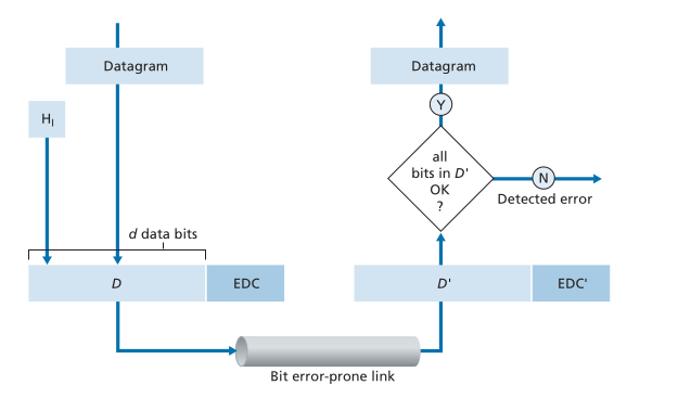
Error detection and correction techniques in the link layer involve augmenting data with error-detection and -correction bits (EDC) at the sending node. The data, along with EDC, is sent to the receiving node in a link-level frame. The receiving node then receives a sequence of bits, D' and EDC', which may differ from the original D and EDC due to in-transit bit flips.
The receiver's challenge is to determine whether D' is the same as the original D given that it has received D' and EDC'. Error detection and correction techniques allow the receiver to sometimes detect that bit errors have occurred. Even with the use of error-detection bits, there still may be undetected bit errors. The link layer also involves a combination of hardware and software, where software meets hardware, to implement error detection and correction services.

Techniques
Parity Checks
Parity checks are a simple form of error detection used in data transmission. In an even parity scheme, a single additional bit is added to the data so that the total number of 1s in the original data plus the parity bit is even. Conversely, in an odd parity scheme, the parity bit is chosen so that the total number of 1s is odd.
At the receiver's end, the number of 1s in the received data plus the parity bit is counted. If the count does not match the expected parity (even or odd), it indicates that at least one bit error has occurred. However, it's important to note that parity checks are not effective under burst error conditions, where errors are clustered together, as the probability of undetected errors can be high.

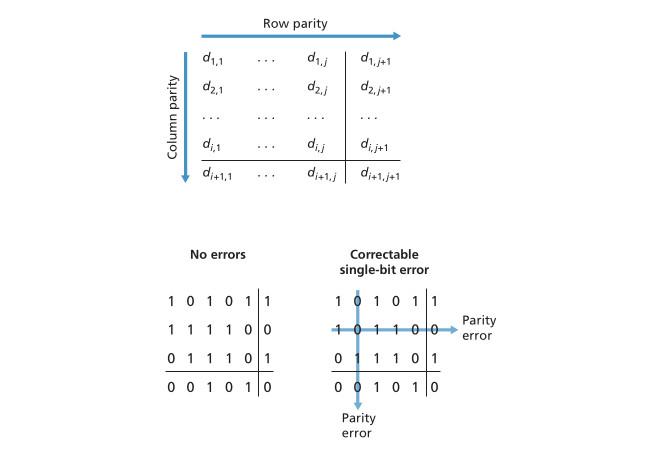
In a more advanced application, a two-dimensional parity scheme can be used. This involves dividing the data into rows and columns, and computing a parity value for each row and column. This allows for the detection and correction of single bit errors and the detection (but not correction) of any combination of two errors in the data packet.

In summary, parity checks are a basic error detection technique used in data transmission to identify errors in the transmitted data by adding a single bit for even or odd parity and checking for consistency at the receiver's end.
Checksums
Checksumming works by treating the data as a sequence of -bit integers, where the -bit integers are summed to produce error-detection bits. The Internet checksum, for example, treats bytes of data as 16-bit integers and sums them to form the checksum.
At the receiver end, the 1s complement of the sum of the received data (including the checksum) is taken, and if the result is all 0 bits, then no error is indicated. If any of the bits are 1, an error is indicated.
This method is used at the transport layer and is implemented in software. In the link layer, more complex cyclic redundancy check (CRC) operations are used for error detection, and these operations are implemented in dedicated hardware in adapters. Checksumming methods provide relatively weak protection against errors compared to CRC, but they require relatively little packet overhead.
Cyclic Redundancy Checks
Cyclic Redundancy Check (CRC) is an error-detection technique widely used in computer networks. It operates by treating the data to be sent as a polynomial, with the coefficients being the 0 and 1 values in the bit string. The key idea behind CRC is to append a set of additional bits (R) to the data (D) in such a way that the resulting bit pattern is exactly divisible by a predetermined bit pattern known as a generator (G). This division is done using modulo-2 arithmetic, where addition, subtraction, multiplication, and division are all equivalent to bitwise exclusive-or (XOR) operations.
The process of error checking with CRC is straightforward. The receiver divides the received data by the same generator pattern. If the remainder is non-zero, it indicates that an error has occurred. Otherwise, the data is accepted as being correct.
CRC calculations are done in modulo-2 arithmetic without carries in addition or borrows in subtraction, meaning that addition and subtraction are equivalent to XOR operations. This method provides a relatively strong protection against errors and is often used in the link layer of network communication due to its efficiency and effectiveness in error detection.
The CRC (Cyclic Redundancy Check) technique involves several steps and equations. Here's a detailed description of how CRC is calculated:
-
The sender and receiver first agree on a generator pattern, denoted as , which is an bit pattern. The most significant (leftmost) bit of must be 1.
-
For a given piece of data , the sender chooses additional bits, denoted as , and appends them to such that the resulting bit pattern is exactly divisible by using modulo-2 arithmetic.
-
The process of error checking with CRC involves the receiver dividing the received bits by . If the remainder is non-zero, an error is detected; otherwise, the data is accepted as correct.
-
All CRC calculations are done in modulo-2 arithmetic without carries in addition or borrows in subtraction. This means that addition and subtraction are identical and equivalent to the bitwise exclusive-or (XOR) of the operands.
-
The sender computes such that there is an such that , where · denotes XOR. The quantity yields the bit pattern.
-
R can be calculated as the remainder of divided by . The algebraic characterization of the bit pattern and the calculation of are illustrated using specific examples in the book. The process involves XOR operations, bitwise calculations, and modulo-2 arithmetic to ensure error detection and correction.1(Cyclic Redundancy Check - Wikipedia)